SPARKS Tutorial Logo Print this

Troubleshooting Breadboard Circuits

Troubleshooting techniques are an application of basic logic. Some people are very good at logic puzzles, and can solve them very efficiently. Most people improve with practice.

The SPARKS troubleshooting challenges are fairly simple. They require you to understand how series and parallel circuits work. Most can be done by measuring the voltage dropped across one or more components, and perhaps lifting a lead or two to measure current.

Series Circuits

The series resistance circuit will be simplest circuit to solve. You are looking for a single defective resistor: either shorted (zero resistance) or open (infinite resistance). You will apply these important facts about series circuits:
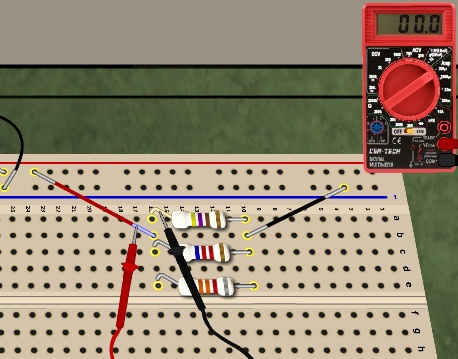
  • In the SPARKS series circuit, if a resistor is shorted (See Figure 1.):
    • There is current through all resistors, and so you will measure some voltage drop across all resistors...
    • ...except the shorted resistor. It will measure zero voltage drop, just like a plain wire.
  • If a resistor is open (See Figure 2.):
    • There is no current, and so you will measure zero voltage across all resistors...
    • ...except the open resistor. It will measure the full battery voltage.
  • Since we know that only one resistor is defective, we can identify the defective resistor with only two voltage measurements in these circuits.

Parallel Circuits

In the SPARKS parallel circuits, a zero-ohm resistor would short the battery, so we've limited the defects to open resistors and out-of-tolerance resistors: either far too large or far too small. Again, you are looking for a single defective resistor. In parallel circuits, the most efficient test is a current measurement, which requires lifting a lead on each resistor to insert the DMM into the circuit, as shown in Figure 3.
  • In the SPARKS parallel circuit, if a resistor is open:
    • There will be no current through the open resistor, as shown in Figure 3.
    • Once discovered, no further measures are needed!
  • If no resistors have zero current, then one resistor has too large (or too small) of a resistance value:
    • The current through the defective resistor will be unusually small (or unusually large).
    • First, estimate the expected currents through each resistor using Ohm's Law. Then compare with measured values. With experience, this will become easier.
    • In Figure 4, the unusually small current through R3 indicates an excessive R3 resistance value. This can be verified with a working ohmmeter.

Series-Parallel Circuits

In circuits with both series and parallel connections, you must apply both of the above techniques. Use the series-circuit principles to test the series resistors, and the parallel-circuit principles to test the parallel resistors.

NOTE: You must be especially careful of the current path when measuring with lifted leads to avoid blowing the DMM fuse.

Practice with the SPARKS circuits will improve your troubleshooting skills!

animated series-troubleshooting-short.gif
Figure 1. Deducing that R1 is shorted.
(Third measurement is unnecessary.)

(Mouse-over to replay animation.)

animated series-troubleshooting-short.gif
Figure 2. Deducing that R2 is open.
(Third measurement is unnecessary.)

(Mouse-over to replay animation.)

 parallel-troubleshooting-open.jpg
Figure 3. Measuring zero current through R1.
(No further measurements are necessary.)

animated parallel-troubleshooting-too-large-R.gif
Figure 4. Finding too small current in R3 indicates
R3 has too large of a resistance value.
(Mouse-over to replay animation.)